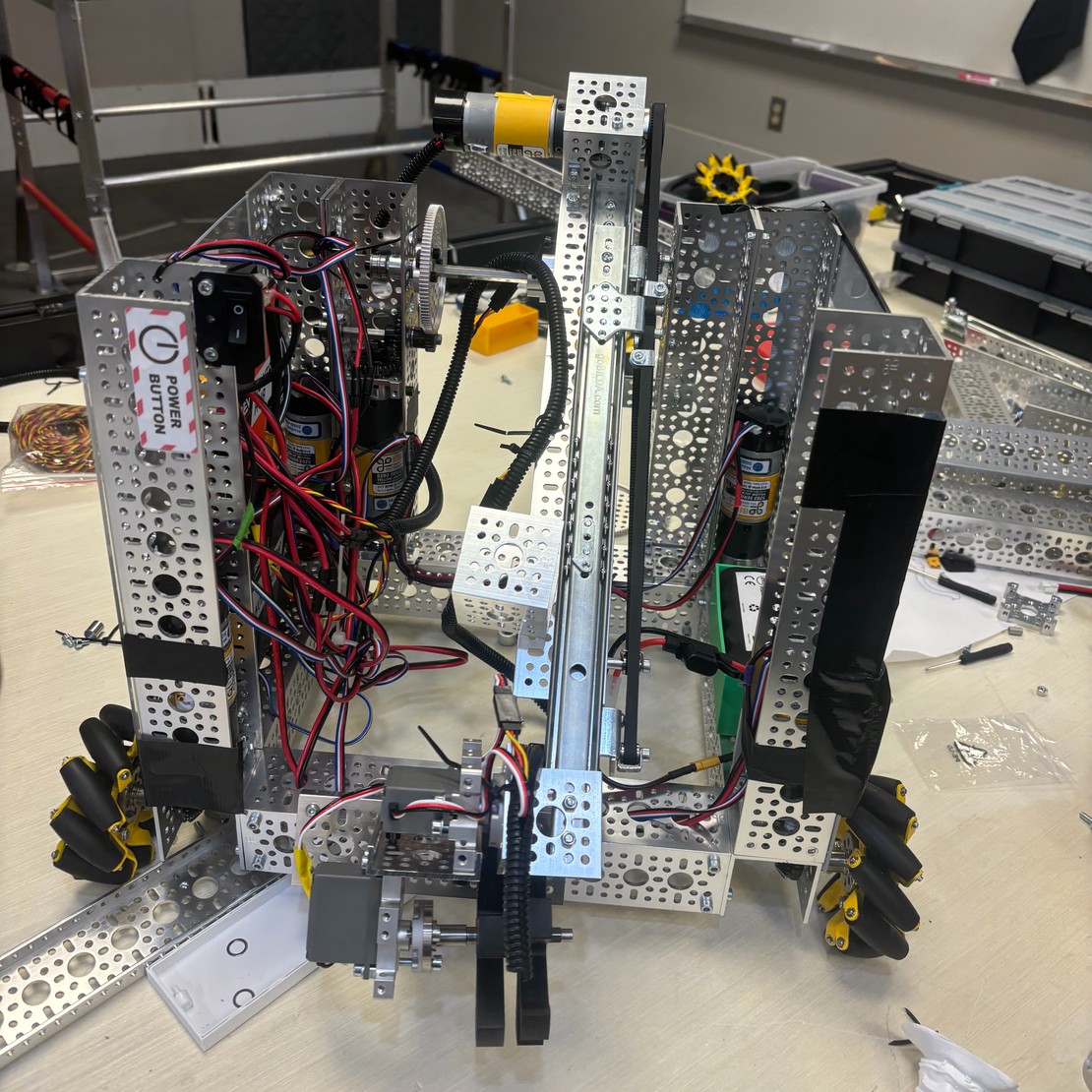
Drivetrain:
Goal was a stable and predictable mecanum drivetrain. Evolved from standard GoBilda geared drivetrain (V1) to center-mounted motors with belt drive (V3). Result: Lower center of gravity, smoother power transfer, and significantly improved stability.
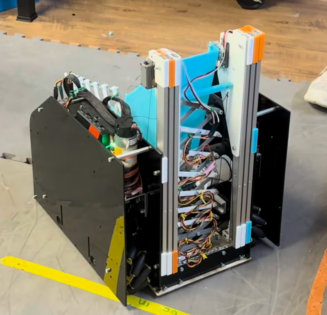
Intake:
Goal was to collect balls from the field and reliably feed the shooter. Design choice: Ramp intake with powered wheels and servos. Iterated through three versions — from ramp with gecko wheels (V1), to adding 2 sets of GoBILDA intake wheels (V2), to extended ramp with a third set of wheels (V3). Result: Consistent intake, reliable ball transfer, and ability to load up to three balls.
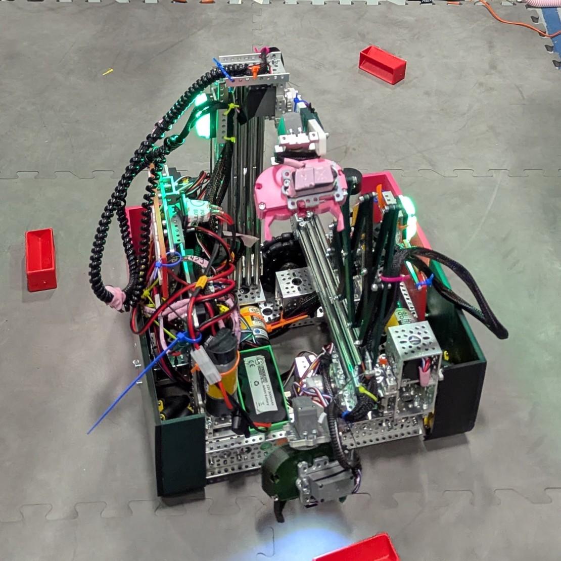
Launcher:
Goal was to score consistently from multiple field locations. Early prototype was a tube shooter with manual feed, but it was inconsistent and location-limited. Transitioned to flywheel shooter for higher consistency. Fixed weak axle mount by adding heat-set inserts.
Current Launcher Design:
• Dual flywheels driven by two 6000 RPM GoBilda motors (1:1)
• Mounted on 3D-printed base attached to rotating axle
• Axle rotated by two 19.2:1 GoBilda motors
Limitations: Motor vibration at high speed, limited max shooting angle at close range.
Planned Improvements: Stiffer 3D-printed mount, motor clamps and steel motor block.
| Drivetrain | Belt-driven mecanum with low-centered motors |
| Programming | Java |
| Intake | Ramp intake with powered wheels and servos (3 iterations) |
| Launcher | Dual flywheel shooter — two 6000 RPM GoBilda motors, 3D-printed base, rotating axle |
| Manufacturing | Custom 3D-printed and laser-cut parts |